
Pressure Swing Adsorption (PSA) nitrogen generators are widely used for on‑site nitrogen production across industries such as food packaging, electronics manufacturing, metal heat treatment, and chemical inerting. Unlike cryogenic air separation or membrane systems, PSA technology separates nitrogen from compressed air at ambient temperature using a physical adsorption process that relies on pressure changes.
Fundamental Principle of Pressure Swing Adsorption for Nitrogen Separation
Kinetic Separation vs. Equilibrium Separation
The core of PSA nitrogen technology lies in kinetic separation – exploiting different diffusion rates of gas molecules into a microporous adsorbent. Carbon molecular sieve (CMS) contains pores of approximately 0.3–1 nm in diameter. Oxygen (O₂) has a smaller kinetic diameter (0.346 nm) compared to nitrogen (0.364 nm). Consequently, O₂ diffuses into the CMS pores much faster than N₂.
During the adsorption step, compressed air flows through a CMS bed. Oxygen molecules rapidly enter the micropores and are retained by van der Waals forces, while the slower‑diffusing nitrogen molecules pass through the bed and exit as product gas. This kinetic effect creates a nitrogen‑enriched stream without requiring equilibrium selectivity – a key advantage of PSA over other adsorption methods.
The Role of Pressure in Adsorption Capacity
Adsorption capacity of CMS follows the Langmuir isotherm: higher gas partial pressure leads to greater oxygen loading on the sieve surface. During the pressurized adsorption phase (typically 5–10 bar g), the CMS retains a large quantity of oxygen, allowing only nitrogen to break through. When the system depressurizes (to near‑atmospheric pressure), the adsorbed oxygen desorbs from the sieve, regenerating the CMS for the next cycle. This “pressure swing” – cycling between high‑pressure adsorption and low‑pressure desorption – gives the technology its name.
Core Component – Carbon Molecular Sieve (CMS)
CMS Structure and Material Properties
Carbon molecular sieve is manufactured by controlled pyrolysis of coal, coconut shell, or polymeric precursors, followed by pore‑size tuning using chemical vapor deposition. The resulting material has:
- Uniform micropore distribution (key for kinetic selectivity)
- High mechanical strength to withstand cyclic pressure fluctuations
- BET surface area typically 400–800 m²/g
- Bulk density around 0.65–0.75 g/cm³
Oxygen Adsorption Capacity and Saturation Dynamics
CMS exhibits a finite dynamic adsorption capacity for oxygen, typically ranging from 2 to 6 mmol O₂ per gram depending on operating pressure and temperature. During each adsorption step, oxygen molecules progressively occupy active sites until the mass transfer zone reaches the end of the tower – a condition known as breakthrough. Once breakthrough occurs, oxygen concentration in the product gas rises, reducing purity. Therefore, the adsorption phase must be terminated before breakthrough, usually after 30–120 seconds, depending on tower size and purity requirement.
CMS Regeneration Mechanisms
Two regeneration methods are commonly employed in PSA nitrogen generators:
- Atmospheric desorption: The tower is vented to ambient pressure, causing adsorbed oxygen to naturally diffuse out of the pores.
- Purge regeneration: A small fraction of product nitrogen (typically 5–20%) is expanded back through the regenerating tower to sweep away desorbed oxygen, accelerating the regeneration process and improving sieve bed recovery.
Modern PSA systems use a combination of both – rapid depressurization followed by a low‑flow purge to achieve complete CMS regeneration within 30–90 seconds.
Dual‑Tower PSA Cycle – Step‑by‑Step Operational Description
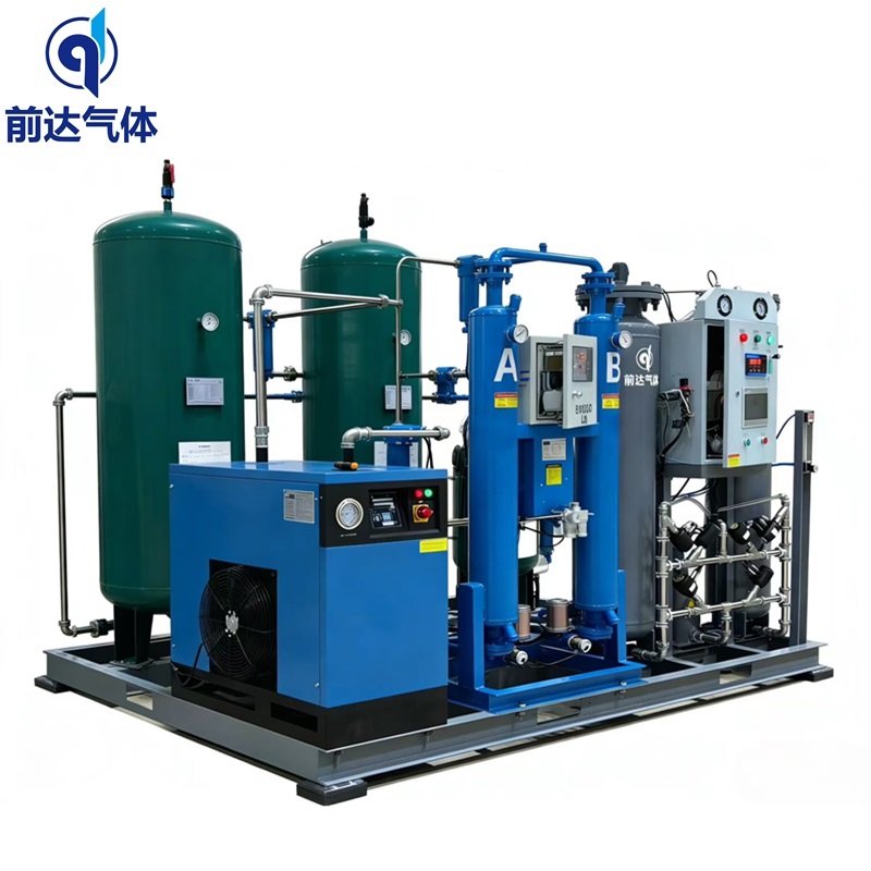
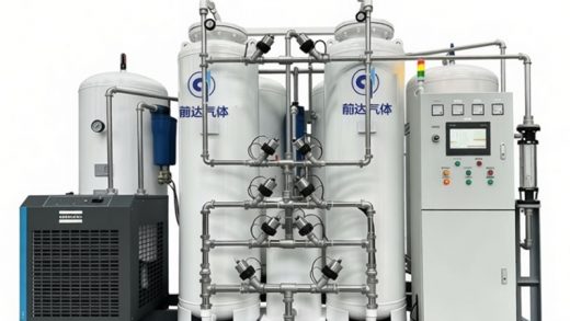
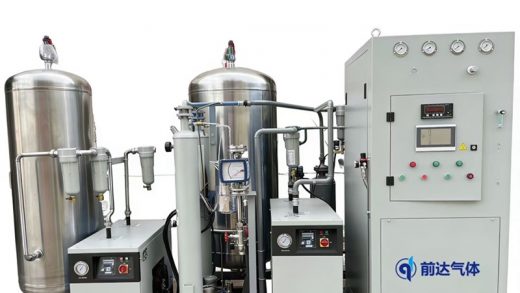
Most commercial PSA nitrogen generators employ two identical adsorption towers that operate out of phase to provide continuous nitrogen flow. Below is a typical cycle using four steps: adsorption, depressurization (equalization), regeneration, and repressurization.
Step 1 – Adsorption (Tower A Pressurized)
Compressed air (pre‑treated to remove oil, water, and particulate) enters Tower A through an inlet control valve. As pressure rises to the setpoint (e.g., 7 bar g), oxygen diffuses into the CMS pores. Dry, high‑purity nitrogen exits the top of Tower A, passing through a check valve to the product buffer tank. Simultaneously, Tower B undergoes regeneration (Step 3).
Step 2 – Depressurization and Pressure Equalization
After a preset adsorption time (determined by purity and flow rate requirements), the inlet valve to Tower A closes, and the equalization valve between the two towers opens. Pressurised gas (mostly nitrogen) from Tower A flows into Tower B, partially repressurizing Tower B and recovering energy that would otherwise be vented. This step typically lasts 2–5 seconds and improves overall efficiency.
Step 3 – Regeneration (Tower B at Low Pressure)
Tower A is then vented to atmosphere through an exhaust valve. The rapid pressure drop to near‑ambient conditions releases adsorbed oxygen from the CMS. Additionally, a small slipstream of product nitrogen from the buffer tank flows backwards through Tower B (or vice versa, depending on system design) to purge residual oxygen. This purge stream is vented to the atmosphere.
Step 4 – Repressurization and Cycle Alternation
After regeneration, the equalization valve closes, and a small product nitrogen bleed slowly repressurizes Tower B to near‑adsorption pressure. Then, Tower B switches to adsorption mode while Tower A regenerates. The complete cycle repeats every 60–240 seconds, with each tower spending equal time adsorbing and regenerating.
Cycle timing example for 99.5% purity nitrogen:
- Adsorption: 60 seconds
- Equalization: 3 seconds
- Regeneration (including purge): 55 seconds
- Repressurization: 2 seconds
Supporting System Components and Their Functions
Compressed Air Preparation (Pre‑treatment System)
Raw compressed air contains oil aerosols, water vapor, and solid particles – all of which degrade CMS performance. A properly designed air pre‑treatment train includes:
- Refrigerated or desiccant air dryer to achieve pressure dew point ≤ -40°C
- Coalescing filters (0.01–0.1 µm) to remove oil mist (<0.01 mg/m³)
- Activated carbon filter for hydrocarbon vapor removal
These components ensure CMS service life of 5–10 years.
Adsorption Vessels (Towers)
Towers are pressure vessels (typically carbon steel or stainless steel) designed to withstand cyclic pressure loads. Internal features include:
- Bed support screens to retain CMS
- Distributors to ensure uniform air flow and prevent channeling
- Bed compaction springs to prevent sieve attrition due to pressure swings
Control Valve Manifold and PLC
A set of high‑cycle‑life pneumatic or solenoid valves direct air flow according to the PLC (programmable logic controller) sequence. The PLC continuously monitors:
- Product nitrogen purity (via an in‑line oxygen analyzer)
- Tower pressures
- Cycle timing
Based on feedback, the PLC can adjust cycle time to maintain purity despite variations in inlet air flow or temperature.
Product Buffer Tank
The buffer tank downstream of the towers smooths out pressure fluctuations caused by tower switching and provides a stable supply of nitrogen to the end user. Tank volume is typically sized to hold 30–120 seconds of average demand.
Performance Parameters – Purity, Flow Rate, and Recovery
Nitrogen Purity Range and Application Mapping
PSA nitrogen generators can deliver purity from 95.0% to 99.9995% (5 ppm oxygen). General guidelines:
- 95–99.0% : Fire prevention, tank blanketing, tire inflation
- 99.0–99.9% : Food packaging, modified atmosphere packaging (MAP), pharmaceutical blanketing
- 99.9–99.99% : Electronics reflow soldering, heat treatment furnace purging
- 99.999–99.9995% : Chemical inerting, laboratory applications (requires post‑treatment or longer cycles)
Trade‑off Between Flow Rate and Purity
For a given CMS volume, higher purity nitrogen is produced at a lower flow rate because more oxygen must be removed from a given volume of air. This inverse relationship is captured by the purity‑recovery curve:
- At 95% purity, nitrogen recovery (N₂ output / N₂ in feed air) can reach 60–70%
- At 99.9% purity, recovery drops to 35–45%
- At 99.999% purity, recovery may be below 20%
This trade‑off is critical for sizing a PSA system – over‑specifying purity wastes compressed air and energy.
Factors Affecting PSA Performance
- Inlet air temperature – Higher temperatures reduce CMS adsorption capacity; 20–35°C is optimal.
- Operating pressure – Higher pressure increases production but also increases energy consumption; typical range 5–10 bar g.
- CMS age and degradation – Gradual loss of selectivity occurs due to pore fouling (moisture, oil) or mechanical attrition.
- Cycle time tuning – Shorter cycles increase purity at the expense of recovery; longer cycles increase flow but risk oxygen breakthrough.
Comparison with Other Nitrogen Generation Technologies
| Parameter | PSA Nitrogen Generator | Membrane Nitrogen Generator | Cryogenic Air Separation |
|---|---|---|---|
| Purity range | 95% – 99.9995% | 95% – 99.9% | 99.999% – 99.9999% |
| Dew point | -40°C to -60°C | -40°C | -70°C to -90°C |
| Start‑up time | 1–5 minutes | <1 minute | Several hours |
| Turndown flexibility | Good (cycle adjustment) | Moderate (backpressure) | Poor |
| Maintenance complexity | Medium (valves + CMS every 5–10 years) | Low (filter changes) | High (turbomachinery) |
| Ideal capacity range | 5 – 3000 Nm³/h | 0.5 – 500 Nm³/h | >2000 Nm³/h |
PSA technology occupies the sweet spot for medium‑purity (97–99.999%) and medium‑flow (10–1000 Nm³/h) applications where on‑site generation is more economical than delivered liquid nitrogen.
Common Industrial Applications
Food and Beverage Industry
Modified Atmosphere Packaging (MAP) uses 99.5–99.9% nitrogen to displace oxygen inside packages, extending shelf life of snacks, coffee, and fresh produce. PSA generators allow on‑demand production without cylinder logistics.
Electronics Manufacturing
Reflow soldering and wave soldering require oxygen‑free atmospheres (typically <10 ppm O₂). PSA systems with a deoxo unit (catalytic hydrogen/platinum) can achieve 99.9995% purity for such critical processes.
Metal Heat Treatment
Bright annealing, nitriding, and sintering furnaces use nitrogen as a protective atmosphere. PSA generators deliver consistent flow at 99.99% purity, eliminating the need for liquid nitrogen storage.
Chemical and Pharmaceutical Inerting
Reactor blanketing, tank padding, and solvent recovery systems utilize nitrogen to prevent explosive atmospheres. PSA generators with remote monitoring and low‑purity (97–99%) options reduce operating costs.
Oil & Gas and Pipeline Purging
Nitrogen is used to purge pipelines before maintenance or commissioning. Mobile PSA containerised systems provide 1000–5000 Nm³/h at 95–97% purity, often replacing expensive liquid nitrogen truck deliveries.
Maintenance and Troubleshooting Best Practices
Daily / Weekly Checks
- Verify oxygen analyzer reading (calibrate as needed)
- Check inlet air pressure and dew point
- Listen for abnormal valve cycling noise (indicates valve wear)
Monthly / Quarterly Tasks
- Inspect pre‑filters and replace if pressure drop exceeds 0.5 bar
- Test safety relief valves
- Log cycle times and product flow rates to detect performance drift
CMS Replacement Indicators
- Gradual purity drop that cannot be corrected by cycle tuning
- Shortened cycle times required to maintain specification (increases energy cost)
- CMS fines collecting in downstream filters (sieve attrition)
Typical CMS service life: 5 to 10 years with proper air pre‑treatment.
The working principle of a PSA nitrogen generator relies on kinetic adsorption of oxygen onto carbon molecular sieve under pressure, followed by low‑pressure regeneration. A dual‑tower design with PLC‑controlled valve sequencing enables continuous production of nitrogen at purity levels from 95% to 99.9995%. Key advantages over cryogenic or membrane systems include rapid start‑up, moderate capital cost, and the ability to adjust purity/flow on‑demand.
For facility managers and process engineers, a solid grasp of PSA fundamentals allows better system sizing, maintenance planning, and troubleshooting – ultimately reducing nitrogen cost per cubic meter while ensuring reliable supply. As energy prices rise and supply chain risks for liquid nitrogen increase, PSA technology continues to gain adoption across manufacturing, food preservation, and chemical inerting applications worldwide.

Hi, this is a comment.
To get started with moderating, editing, and deleting comments, please visit the Comments screen in the dashboard.
Commenter avatars come from Gravatar.